SignTorch
Artist
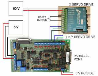
Now we can connect the axis drive output pins on the BOB to the servo drive inputs.
Turn everything off. Do not connect a motor at this time.
On both servo drives turn all the DIP switches on, except turn switches 7 and 10 off.
Connect each step, dir, and gnd from the BOB to step, dir, and com on each servo drive as shown below.
Connect the reset button from ENC 5V to ERR/RST on each servo drive.
Connect motor power to terminals 1 and 2 on the servo drive.
Connect motor power ground to 5 V ground on BOB.
Power up, start Mach3 and press reset in Mach3.
Set step jog mode with .1" jog increment.
That will send about 212 step pulses per jog.
So that if we jog once we get a warning, and if we jog twice we get a fault because the number of steps taken will exceed the 256 step following error limit that is set by DIP switches 4 and 5.
The servo drive power light should be on.
The servo drive fault light should be on.
Press the reset button on each servo drive.
The fault light should go off and the IN POS light should come on.
Now jog each axis once by pressing an arrow key once.
When the drive gets the first step signal, the IN POS light should go off and the WARN light should come on.
If you jog twice, it exceeds 256 step signals in the same direction, the WARN light will go off and the FAULT light will come on.
At that point the servo drive shuts down because it is out of position. Press the servo reset button to reset, and IN POS light comes on.
Jog once, the WARN light comes on. Jog once in reverse direction. IN POS light comes back on.
Test both drives by jogging their respective axis. X and Y should both behave the same way.
Now we know that the BOB is sending the step/dir signals and the drives are receiving them.

