Connect Encoders to Servo Drives

Connect Encoders to Servo Drives

SignTorch

Artist
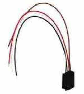
Now we have to tap into the wire harness to route each encoder's wires to it's respective servo drive.

The harness has two sets of identical wires for the encoders so be sure to route the right encoder to the right drive.

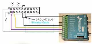
I will show the X axis encoder and the Y axis is identical, except X goes to far left 4 pins and Y goes to the next 4 pins to the right of X in the wire harness connector.

The harness wire colors are the same on both encoders. White goes to Channel B, Grey is no connection, Purple goes to Channel A, Yellow goes to + 5 V.

A brown wire (and a shield drain wire) routes from each encoder to pins 5 and 6 in the connector. That is the ground lug. Several grounds and all cable shield drain wires in the harness route to that ground lug.

Our encoder wiring to the servo drive should be shielded cable with the shield grounded at that ground lug at the connector.

In a previous schematics we ran a ground from the BOB to the servo drive COM terminal, but that terminal is isolated from the other grounds such that it does not form a ground loop.

In a previous schematic we showed 5V and 60 V grounds joined together, those should actually be joined at the ground lug.

Do not connect any motor armature wires at this time.
servo encoder.jpg
 
My dip switch settings are all on except 7 and 10 are off.

DIP Switches

SW1
Not used

SW2, SW3 MUL1 and MUL0 respectively, set the G320X pulse multiplier
SW2 “ON” and SW3 “ON” = Step pulse times 1 (default)
SW2 “ON” and SW3 “OFF” = Step pulse times 2
SW2 “OFF” and SW3 “ON” = Step pulse times 5
SW2 “OFF” and SW3 “OFF” = Step pulse times 10

SW4, SW5 SR1 and SR0 respectively, set the G320X following error limit
SW4 “ON” and SW5 “ON” = +/- 256 count following error limit (default)
SW4 “OFF” and SW5 “ON” = +/- 512 count following error limit
SW4 “ON” and SW5 “OFF” = +/- 1024 count following error limit
SW4 “OFF” and SW5 “OFF” = +/- 2048 count following error limit

SW6 HEDS
SW6 “OFF” = Default
SW6 “ON” = Turned on if using encoders with HEDS optical heads or open collector encoders. Disables encoder failure detection allowing user to run encoders that don’t have line drivers or active pullup.

SW7 TORQ
SW7 “ON” = Use LIMIT trimpot setting only (default)
SW7 “OFF” = Allow 20A for 1 second, then use LIMIT trimpot setting

SW8, SW9, SW10 GAIN2, GAIN1, and GAIN0 respectively, set the current mode servo gain
SW8 “ON”, SW9 “ON”, SW10 “ON” = Lowest gain
SW8 “ON”, SW9 “OFF”, SW10 “ON” = Low gain
SW8 “ON”, SW9 “ON”, SW10 “OFF” = Medium-low gain
SW8 “ON”, SW9 “OFF”, SW10 “OFF” = Medium gain 1 (default)
SW8 “OFF”, SW9 “ON”, SW10 “ON” = Medium gain 2 SW8 “OFF”, SW9 “OFF”, SW10 “ON” = Medium-high gain
SW8 “OFF”, SW9 “ON”, SW10 “OFF” = High gain SW8 “OFF”, SW9 “OFF”, SW10 “OFF” = Highest gain
 
Servo Encoder

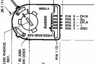
The OEM servo encoder is HEDS-5540#A06 - 500 ppr 1/4" 3ch - datasheet attached

requires 2.7 kΩ (± 10%) pull-up resistors on output pins

https://www.digikey.com/en/products/detail/broadcom-limited/HEDS-5540-A06/1990420?utm_adgroup=Sensors & Transducers
---------------------------------------------------------------------------------------------
Equivalent servo encoder is HEDS-5600#A06 - 500 ppr 1/4" 2ch - datasheet attached

not required but 3.2 kΩ pull-up resistors on output pins are recommended

[BCOLOR=rgb(252, 252, 255)]https://www.mouser.com/ProductDetail/Broadcom-Avago/HEDS-5600A06?qs=RuhU64sK2%2Bv2T8lkYg1eog==[/BCOLOR]
---------------------------------------------------------------------------------------------
this HEDS5 and HEDM5 series of encoders are all very similar and are largely interchangeable - the M has mounting ears

the 3 channel models call for using guide pins or HEDS-8910 alignment tool to mount the encoder concentric with the shaft, but that is only because they have a slightly better potential pulse width error tolerance, keyword is potential because they all use the same housing and code wheel, so they all have virtually the same performance depending on mounting accuracy, they can withstand a generous margin of error in mounting because the code wheel just has to be in the optical slot without making contact, and the error induced by mounting inaccuracy is so microscopic it hardly matters for general CNC purposes, but it is prudent to use the alignment tool or a similar tubular guide to mount the encoder as close to concentric with the shaft as reasonably possible just for good measure, but they can be mounted with double sided tape anywhere near concentric without compromising function or accuracy enough to make much difference

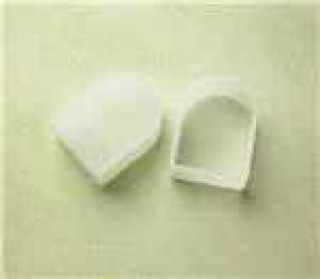
you have to loosen the code wheel set screw to install or remove the housing because the code wheel has to come off or go on with the housing - if you remove the housing without loosening the code wheel it will bend the code wheel where it extends into the optical slot that is attached to the housing - rotate the screwdriver slot clockwise to two dots to lock the housing to the base - rotate counterclockwise to one dot to unlock and install or remove the housing - you usually have to pry the housing up gently to remove it from the base because they are snapped together

the code wheel set screw is #2-56 - hex wrench size is .035"

The datasheets don't show the #A06 option for 1/4" shaft but that is correct


2023-03-30_20-10-56.jpg
 

Attachments

You must be signed in to view attachments...
  • HEDS-5600#A06.pdf
    1.6 MB
  • av02-1046en_ds_hedm-55xx_2014-11-20.pdf
    461.9 KB
Back
Top Bottom