SignTorch
Artist
We have to cut the plug off of the Z stepper motor because it only has 3 wires to the motor.
Just cut it midway between the motor and plug then run a new 4 conductor cable to the motor. That leaves the existing wire and plug for other purposes.
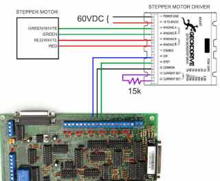
The diagram shows the Gecko G213V stepper driver. Any bipolar stepper driver should work (wiring may be different).
First remove the cover and make sure the step multiplier jumper is set for half stepping. Mine came that way.
Then, you need a current set resistor. I used a 15k resistor for about 1.75 amps.
I also tried a 47k resistor to get about 3.5 amps. Over 3 amps and the driver recommends heatsinking.
More resistance means more power but in either case my motor would not run much faster than 70 inches per minute.
The Step signal goes to pin 6 on the BOB, Dir goes to pin 7 on the BOB, and common goes to ground on the BOB.
Motor power comes from the main power supply.
Make sure it jogs in the right direction and stops when the limit switch is tripped.

